

Design Analysis
Q-1 How will you detect the holes using the sensors available to you in the kit?
We will be using the following sensors for detection of holes :
We will be using the following sensors for detection of holes :
· SHARP IR RANGE SENSORS(GP2D120) INTRODUCTION:
We are using the sharp IR range sensors GP2D120. The Sharp GP2D12 infrared ranger is able to continuously measure the distance to an object. The usable range is 10 cm to 80 cm. The device generates an analog voltage that is a function of range, and the output voltage can be measured by an analog-to-digital (ADC) input line on fire bird 5.
How it works
The device emits a pulsed infrared beam at a wavelength of 850 nm ± 70 nm. If an object is within range and in line with the IR beam, reflected light forms an image on a linear CCD array in the receiver.
Triangulation is then used to determine range. Readings are updated at a rate of approximately 24 Hz. The detector is relatively insensitive to ambient lighting, as well as reflectivity of the object being detected. It is possible to detect relatively dark objects in full sunlight.

Triangulation Method:
The output voltage is a nonlinear function of the distance from the object to the receiver. In figure 1, the curve of voltage vs. distance was taken from Sharp documentation.
**Note that objects less than 10 cm away can look like objects at longer distances. This ambiguity needs to be taken into account if objects are allowed to be closer than the 10 cm threshold.

Triangulation Method:
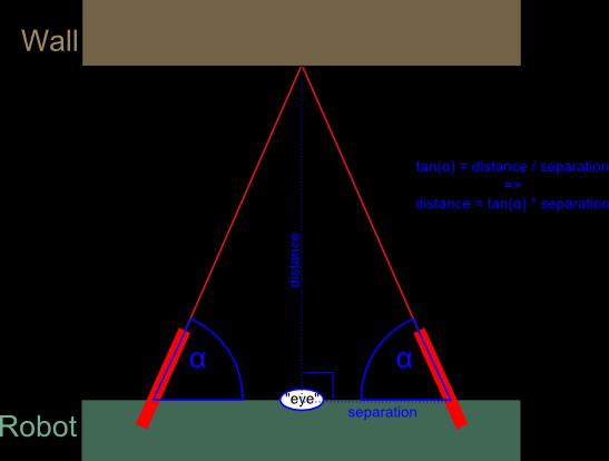
In trigonometry and geometry, triangulation is the process of determining the location of a point by measuring angle to it from known points at either end of a fixed baseline, rather than measuring distances to the point directly. The point can then be fixed as the third point of a triangle with one known side and two known angles.
The figure 2 shows the principle of triangulation method used in sharp sensors to calculate distance from the object
Q-2
Draw a labeled diagram to explain how you have planned
to place the sensors on/around the robot? (15)
We are using only the two sharp IR range sensors provided in the kit for detection of hole. The figures 3 and 4 accurately determine the position of the two sharp sensors with respect to the arena and the position of the robot


JUSTIFICATION:
We have decided to place
the sensors in the position shown above ,because it will help us detect the
hole with great accuracy and prevent us from missing any hole .The sharp
sensors have been adjusted in our arrangement at a height, such that it gives a
great variation of output analog voltage when it moves from the thermocol
surface towards a hole
.This output analog voltage is then feed to
the respective ADC converters which gives the approximate distance of the
surface from the sharp sensor.(*in our arrangement ,a value less than 85
represents the presence of the thermocol surface underneath and is indicated by
a digital value 0, will a value returned by sharp sensor above 120 represents a
hole and is indicated by a digital value 1.Thus whenever the value of the
sensor goes from 0 to 1 it represents the presence of the hole underneath.)
DIFFICULTIES:
We had to place the sensor
in such a way that the surface is always at a distance more than 10 cm ,as we
have discussed earlier that objects at a distance closer than 10 cm can cause problem .
Q-3
Teams have to prepare the dispenser mechanism for dropping seeds
into the holes.
a) Choose an
option you would like to use to position the dispenser mechanism on the robot. (5)
1. Front 2.
Back 3. Right/Left 4. On both sides
Answer: On both
sides
**We have placed our mechanism at the center of the robot and have drawn to pipes, such
that they are exactly over the left and right whole .thus we have selected the
4 option.
We would be placing the dispenser mechanism on the robot as shown in
the figure 5
a) Draw a diagram to show
the dispenser mechanism and how it is mounted
on the robot. (15)
The following figure determines the position
of our designed mechanism for dispensing seeds one by one. We decided to mount
our mechanism in the position shown after taking into consideration the
following factors:
JUSTIFICATION:
We decided to place the
mechanism on both sides of the robot such that the robot does not needs to
deviate from the line. Thus the robot can remain in its position and can sow
the seeds in the intended hole, preventing any error or confusion due to deviation
from the line.
Other factors considered to decide the position of the mechanism:
·
Weight balancing :
Initially we had decided
to place two storage and dispensing mechanism on both sides of the robot i.e.
left and right, but taking into consideration the weight balancing of the robot
we decided to use a single storage and dispensing mechanism such that the
overall weight of the robot is balanced and took out two outlets from the it
one for sowing seed in the left and the other for sowing in the right hole as
shown in the figure 5.Besides this it also provides one more advantage that
,the overall load on the motor is reduced thereby reducing the current drawn by
the motor.
·
Ease of mobility:
As discussed earlier we
changed our plan of using 2 storage and dispensing mechanism, because it also
brought a large amount of constraint on the motion of the robot. Thus reducing
the ease with which the robot can move around the arena.
· Stability
of the structure:

Figure 5
WORKING:
Our mechanism consists of three
major sections:
·
Seed Storage unit: The storage unit is basically used to store
the seeds required for sowing .The unit is designed to store a maximum of 88
seeds .it consists of 8 tubular cylinders separated by 45 degrees , each tube
having a capacity to store 11 seeds each as shown in the figure .it is always stationary.

·
Temporary Single seed separation unit:
It basically consist of
two parts .one part consists of two disk 1 and 2 as shown in the figure which are coupled together and are
connected to the stepper motor .in between this two disk is another storage
unit as above but has the capacity to hold only one seed at a
time .the disk
1 and 2
each have a
single hole in
them along the
rim of the disks
,separated by 45 degrees .the upper disk has
a hole 45 degree ahead of the hole in the
lower disk. the hole in the disk 1 allows a seed to come in the single
seed storage unit , when it is rotated by 45 degrees the hole in the disk 2
comes directly below the seed and thus the seed finally comes out of the
storage unit and is then feed into the dispensing unit
.this process is continued to
drop one seed at a time.
Thus the above mechanism does not allow more then one seed to fall at the
same time, preventing any unwanted loss of seed.

Figure 6

Figure 6
·
Dispensing unit: After the seed comes in this unit, it is
directed by the servo to the respective hole either left or right. The position
of the servo motor is shown in the
figure 7.We have used the servo motor to rotate the flap connected to
its shaft a shown in the figure 8.The flap is rotated to decide in which hole
does the seed actually go into, which is decided by the program .The figure 9
shown how the seed is diverted towards the left hole by the flap. Similarly the
seed can be made to go in the right hole as
well.
 FIGURE 7

After all of this the seeds are dropped in the hole and the robot moves ahead
 Figure 9Q-4
Choose the actuator you will use to design the dispenser mechanism. (5)
Figure 9Q-4
Choose the actuator you will use to design the dispenser mechanism. (5)
1. DC-Motor 2. Servo Motor 3. Stepper
Motor 4. Others Answer: Stepper motor and servo motor both.
Justify your
answer by stating the advantage of the chosen actuator over others. Also give reasons
for not using other actuators.
JUSTIFICATION:
We are using both a
stepper motor and a servo motor in our overall dispensing mechanism ,but the
stepper motor forms an much more integral part of our mechanism .The Stepper
motor is used to rotate the disc in our mechanism by a specific angle depending
on the number of seeds to be dropped in the hole .We decided to use a stepper
motor ,because we required the differentiating disc
shown in the figure 6 to be rotated by a complete 360 degree and the servo
provided in the kit can rotate only a angle of 180 degrees .
Stepper Advantages:
Stepper motors offer several
advantages over servo motors:
·
larger
number of poles
·
Easier
drive control.
·
The design of the stepper motor provides a constant holding torque
without the need for the motor to be powered.
·
The torque of a stepper motor at low speeds is greater than a servo
motor of the same size.
·
One of the biggest advantages of stepper motors is their relatively
low cost and availability.
Conclusion:
For selecting the
best motor for our application, we took into consideration the key design
criteria for our system including
cost, positional accuracy
requirements, torque requirements, drive power availability,
and acceleration requirements. Overall, servo motors are best for high speed,
low torque applications while stepper motors are better suited for lower
acceleration, high holding torque applications.
Thus we decided to use a stepper motor for rotating our
disc as it required a high holding torque and their was no need of speed in
this application.
Algorithm Analysis
Q-1 Draw a flowchart illustrating the algorithm used to
complete the entire
task. (40) We have
divided the overall programs into three sub sections as follows:
·
MAIN
·
LINEFOLLOWER:
In the line follower
algorithm below the sensors are represented by the terms left ,right and center respectively .while black and
white terms are used to indicate the colour of
the surface.
MAIN PROGRAM

LINE FOLLOWER FUNCTION

SEED SOWING FUNCTION

No comments:
Post a Comment