Sunday 30 November 2014

EAGLE PCB DESIGNING TUTORIALS FOR BEGINNERS-1

EAGLE FOR BEGINNERS

        In my last post we had gone through a basic light triggering circuit Hope you are happy with your first "TechProject"now lets go one step ahead and we will learn the basics of a PCB designing software "EAGLE".
After this you can actually design a circuit of your own and get rid of those messy SOLDER'S and WIRE'S and give your circuit a professional look.

Lets GET started

So Eagle is basically a software that can be used to design your PCB(printed circuit board) that can be latter printed either at home or can be printed at some pcb printing shop to get more professional and accurate.

STEPS:

  1. Download and install Eagle.eagle is not a free software but you can get the lite version for free which is sufficient as of now.                                                                                                                                                                                                                                                                                  you can get the eagle lite version at the below link:                                              http://www.cadsoftusa.com/download-eagle/freeware/                                                                                                               
  2. Open the eagle software,Following screen will appear on the desktop.        


       3.  Now click on File and then  new and then open schematic.


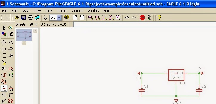
      4. Then the following window will appear before you
             The schematic is a place where you can add your components and then make the connections as you do normally in any simulation software or say as the circuits you make in your book.You can see a simple schematic of voltage regulator in the image.


     5. COMMANDS:
Now lets look at the important commands that will be usefull while designing the schematic


  • MOVE:
                    The move command is used to move the component in the schematic frame and arrange the components as required .It should be noted that the arrangement of componet in the schematic is not so important as the final arrangement is done in the board file only, the schematic is just for reference.
  •         ADDING COMPONETS IN THE SCHEMATIC:
                      This command can be found in the tray on the left of the screen  click this to add new componets ,Clicking ADD open the following window.

 Then click on the componet required and then Click OK to add the component in the schematic.


  •     WIRING UP:    

                    Now after adding the componets you need to wire them up you will see the LINE icon on the tray  clicking it enable the wire and then using your mouse you can connect the wire between required terminals.


       6.   LOADING LIBRARIES:

   Click on 'LIBRARY' tab and then 'USE' the select all the libraries and then add them .This needs to be done when you open Eagle for the first time.
  • ADDING NEW LIBRARIES: Click on 'LIBRARY' then 'USE' you can then find the link of the lbr folder on your PC
  • Place the dowloaded lbr file in this folder and then restart Eagle ,if required you may need to load the library for first time by following the procedure above.
Now you are ready to design your own circuit.

THIS ARE THE BASIC COMMAND THAT YOU NEED TO NOW IF YOU ARE A BEGINNER IN EAGLE THEN THE REST CAN BE LEARNT AS YOU GO ON PRACTICING BY DESIGNING NEW CIRCUITS IN EAGLE .

Now you are ready to design your own circuit
     HOPE THIS HELPS!!!!!!!!!!!!!!!!!!!

                                                             THANKYOU

Wednesday 19 November 2014

MY First "TechProject"

Hello Everyone,

          Way back in my College Days When i was studying for my HSC exam in 2012, It was the time for me to submit my Electronics projects .But I was nowhere with the project , as at that time the only thing in my life was just Study Study and study!!!!! .At that time i had no interest in Electronics and also Computer programming. Then i was allotted a project by my  professor Titled "LIGHT SENSITIVE SWITCH"  and this was the project which actually brought me closer to Electronics.
The project was simple but still very important for me, as it is what has helped me discover my true passion in life and  and , it is after this project that i took up electronics as my Hobby and started going deeper in this field.

So lets get started up with this SIMPLE But  IMPORTANT  project which may become  instrumental in helping someone like me discover his/her own passion.


            LIGHT SENSITIVE SWITCH           

The project as the name suggest is nothing but a switch which is triggered by Light.So lets begin with the basic working of this "TechProject".

  1. IntroductionThe most important part of the above project is a LDR-Light Dependent Resistor.The LDR is a resistive element Whose resistance decreases with the increase in Intensity of incident Light.So it can be said that a LDR is a Photoconductive device.So a LDR acts as a sensor to tell our circuit that the Light in the surrounding is increasing or Decreasing.Then depending on the input from LDR the remaining circuit does its task ahead                                                                                                                                                                                                
  2. Components and Circuit:
The Circuit for the above project is as follows:


The Circuit has been taken from Visha Electronics Kits ,I have used this circuit to explain because this was the circuit which i had actually made as my project.

The Basic components are:
  • IC 555:                                                                                                                            If you are new to electronics then remember that in your starting years this IC will be very important for you ,because it has so many applications that you will actually fall in love with this IC as i had years ago.It is 8 pin IC in DIP package(A package is basically the shape of the IC DIP-dual inline package is the most useful for beginners and then you can go ahead with much complex ICs with SSOP,SOIC etc packages.).IC 555 is generally used in two modes Monostable and Astable mode in above Circuit we will be using the IC in monostable mode. In monostable mode whenever the voltage at pin 2(Trigger) falls below Vcc/3 then the output of the IC pin 3 Goes HIGH for a time period decided by the RC circuit values.In above circuit the values of R1,R2 and C1 determine the time period But if the Pin 2 is kept below Vcc/3 then the Output remains HIGH irrespective of RC Circuit values.                      
  • Relay:                                                                                                                           It is a Electro-magnetic switch.It gets actuated when given a Electrical Signal.It looks small but is the most important and most widely used element in most of the circuits today.It works Similar to our old bells.It has a arm which is said to be in NC(Normally open position) when unexcited, and a coil which when energized forms a electromagnet and attracts the arm towards it ,the arm is now said to be in NO(Normally open position).The following animation explains it aptly.                                                                                     
  • LAMP: We will be using a Lamp in our circuit as a load to indicate the switching action of the LDR


       3. Working:  
                      Under normal conditions when the LDR is present in daylight it has a low resistance and the value of R1 is so adjusted that voltage across LDR is less than VCC/3 thus the 555 is triggered and the output pin3 goes HIGH.When a intruder comes in and its shadow falls on the LDR or if the Daylight fades than the resistance of LDR increases and thus voltage across it goes above Vcc/3 and thus the output goes low now the output will remain low unless the Daylight intensity increases again.
       When the Output is High the Diode is forward biased and the relay is not Triggered and thus lamp remains off When the output goes Low the relay coil is Energized and thus the relay arm is attracted to NO position thus completing the circuit and hence the lamp glows.

     4.  Specifications and Cautions:
  • The general relay rating is 230V and 3/6A so see to it you don't exceed any one of the above limit while trying to modify the circuit.
  • Keep the lamp away from the LDR or it may itself trigger the LDR.
  • If possible you can use a transformer and a Bridge rectifier circuit to obtain a 12 V Dc supply.it would be more interesting,I did the same instead of using a battery to trigger the relay.
   5. Materials:
  1. R1-pot of 1Mohm
  2. R2-1Kohm
  3. LDR
  4. C1-0.1uf
  5. IC 555
  6. LAMP
  7. Relay
  8. Diode(IN4007 preferred)
  9. 12 or 9 V battery to trigger the relay(a 9V transistor battery will work)
    6.  Applications:

  • To detect the Intensity of light in the surrounding and provide automatic lighting system.
  • To detect the presence of a intruder when the shadow falls on the circuit.


So finally You are done with Your first ever working "TechProject"!!!!!!!!!!!
A simple "LIGHT SENSITIVE SWITCH"
I Hope this help's you in some way!!!!!!!

THANKYOU