Monday 22 December 2014

ARDUINO TUTORIAL FOR BEGINNERS - 2


  Hello,
            
              In the last post we have answered some of the most common Frequently asked Questions(FAQ's) about Arduino's.Hope that now you are ready with the basic setup for starting arduino,lets have a quick look at the requirements

  1. ARDUINO SOFTWARE IDE
  2. ARDUINO BOARD
  3. MOST IMP "SOME INNOVATIVE IDEAS IN YOUR MIND"
   Now that you are ready,Lets get started.

  1.  Open the Arduino IDE on the desktop 
Now lets get into the command icons that you can see on the top left corner of the desktop

      
     COMPILE :If you have done some kind of programming ever than you must have heard this word some where ,a compiler converts the HIGH LEVEL language code into the MACHINE LANGUAGE(HEX file)  which the arduino can understand

You can have a more knowledge on compiler and interpreter from the following link

     UPLOAD :This is used to transfer the code from the PC to the Arduino Board.So the upload is actually two step process in which the code is COMPILED first into the machine language and then BURNED onto the Arduino MCU(by the way arduino UNO uses the ATMEL AVR 328P-PU Micro controller )

rest of the command are self explanatory.


     2.   Now lets Start learning the Arduino "SYNTAX"

Open the "BLINK" example in Arduino the best one to start with!!!!


Lets see what the code has?????
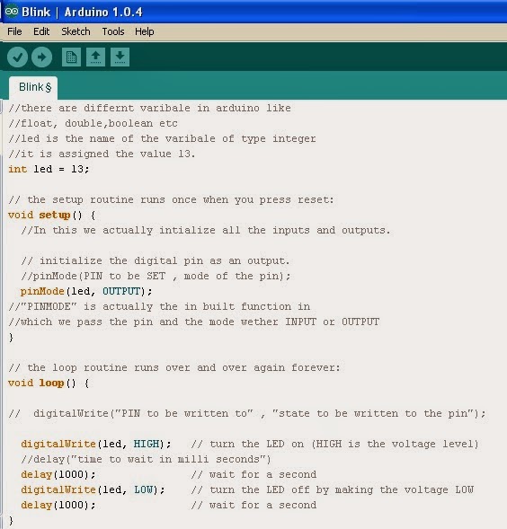


The definition and significance of each line has been explained in the figure above

     3.  Let us list down the important Functions and Key words used in the above code:

  1. "int" :It is a type of variable 
  2. "void" : It is the type of function return,when ever we define a function in any language we need to define the type of value it gives to the output.if the function does give any value in return we name the return type as "VOID" 
  3. "setup":It is the function of Non-return type which runs for one time whenever the arduino is reset or powered.Thus it contains the intinitialization of all the things used in the code.
  4. "pinMode":This is a function which is used to define the behavior of a pin ,the pin can act as either INPUT or OUTPUT.
  5. "loop":This function is operated after the setup function has been run once and then continues to run for infinite time or until the arduino is reset or switched off. Thus it is similar to a while loop in "C"
  6. "digitalWrite":This is a function used to write a digital value (HIGH or LOW and 0 or 1) to any pin initialized in the setup as OUTPUT.    
  7. "delay()": This function is used to produce a delay in the execution of code,this is required when taking input from a sensor in order to provide settling time to the sensor and give new reading.

     4.  Practice Question:

Write a code to blink the LED connected at pin number 3 of Arduino uno and with a ON time of  700 ms and OFF time of 200 ms ?


After you have all of this please watch this video to get the things much more clear.

Tutorial 01 and 02


Saturday 20 December 2014

ARDUINO TUTORIALS FOR BEGINNERS-I


I have been working with Arduino's for some two years now and have completed many interesting projects using this simple micro-controller Board ,so before i start posting my projects here i would like to post a series of arduino tutorials for those new to the world of this magical device.


"ARDUINO-FAQ'S"

So the first question that many people ask me when they hear about arduino.

 1) What is this ARDUINO????

so the answer is simple---wikipedia says this.
  1. "Arduino is a family of single-board micro controllers, intended to make it easier to build interactive objects or environments. The hardware consists of an open-source hardware board designed around an 8-bit Atmel AVR micro controller or a 32-bit Atmel ARM".
so putting this in simple words,Arduino is a "MICRO-CONTROLLER" that has a Programming Environment (IDE)  provided by the arduino people which is so simple to use that you will never forget it.


So now lets get started!!!

2) What do you require to begin learning arduino?????

  • ARDUINO software ----->get it on the following link                                       http://arduino.cc/en/Main/Software
 
  • A ARDUINO BOARD-----> you can search for store nearby or even order it online arduino is easily available,because it is very much popular and used among developers because of its simplicity.
  • A COMPUTER

  • Very important---"Some innovative ideas in your mind"
That is it,this is all that you need for learning arduino

3) Which Arduino to select??????

      If you are Beginner than the best to start up with is arduino "UNO" it is sufficient for beginners and can be used for complex task as well because this is what i used for most of my project's and the second reason it is "CHEAP" as compared to other arduino boards so not a big issue if yu fry up your new arduino "UNO" 

 
4) What is the Difference between a Micro controller and a Micro processor?????

BRAIN POWER:

    So putting it in simple word's for beginners, A micro controller has low processing power which means it cant process large and complex tasks e.g processing a image, but a micro processor can do very much complex task with ease.

MUSCLE POWER:

      BUT the micro processor  does not sufficient power to drive external devices that is it cant control external devices easily but the micro-controller can do so and thus is named a controller while a processor is called so because of its high processing power.

So your Arduino is a  Micro controller and can drive external devices like a LED,Transistor,MOSFET, and even servo motor but a processor cant.

So in simple words a micro controller has muscle power but has low brain power while a processor is sharp at brain but has low muscle power 
the following video may clear it furthur.


Hope that most of your questions as regards to arduino are solved now and in the next post we will go through the arduino IDE and learn the simple arduino programming SYNTAX.

Friday 5 December 2014

PRINT YOUR EAGLE PCB ON A PAPER.

EAGLE PCB DESIGNING TUTORIALS FOR  BEGINNERS-3 

PRINTING IT ON THE PAPER:

In the Previous segment of this series of eagle post we had come uptil the eagle board file of the circuit, Now in this post we will go through the steps to be followed before we transfer this .brd file on a actual board.

  1)  open the board file we have designed and now we need to do some settings before we actually print this on a paper.

2)   Your .brd file would  look something like  this.
But if we take the print directly the components that are visible will also get printed on the paper and thus will cause unnecessary shorts in the circuit.To prevent this we need to eliminate the components from the brd file how do we do this???????


    ANSWER:
      {   I hope you remember the "LAYER" command i had explained in earlier post ,if not just scroll up and read it out for your reference.}
   
     Now open Layer command and then click on "none" and then "apply" Now you would see that the entire brd has become empty.
Now select the following layers by clicking on the number adjacent to them,the selected layer will be highlighted with a blue colour.
  • TOP
  • BOTTOM
  • PADS
  • VIAS 

When you are done the final brd should look like this.
{don't worry about the warning i closed my schematic by mistake so the annotation is not allowed,you may get it sometime so don't worry about it and again open the schematic}

 3)  Now there are two printing methods:

            1)Single PCB:

                                In this method we directly take the print of the file and thus have only a single PCB on a page. 
   ------->click on "file" then click "print"
and then select the following options:
  •  BLACK
  • SOLID
don't select other options and keep all other field as in the photo.

 {Remember to set the paper to A4 size and the scaling factor to 1 other wise the component wont fit on the PCB.}
   
             2) Multiple PCB on single PAPER 

                        In this method we can actually get multiple images on a paper of the same circuit or even two different circuit this will be useful when you are printing a number of circuit as it will save the number of pages required .

follow the below steps:
  1.  EXPORT
  2. IMAGE
  3. GIVE A NAME AND SET THE RESOLUTION AND SELECT MONOCHROME


{Before exporting the image set the background to white so that you don't get a inverted image,To do this follow this steps:
"option"--->"user-interface"--->"Background"--->"White" }

Now open your image
 4) Now copy this image into a word file then set the paper to A4 size by placing a A4 size paper o the screen and then resize the image to required dimension.While resizing see to it that the IC base is fitting or not by just placing it on the screen.

5)Now then Copy the image and then paste it as many time you want.


{Remember the following steps:
  • Set paper size to A4 by placing the A4 paper on the screen
  • resize the image until it matches the component size}
 Now you are ready just go and take a print.

Hope this helps you.

Wednesday 3 December 2014

EAGLE PCB DESIGNING TUTORIALS FOR  BEGINNERS-2(6-STEPS)

   In the previous post we had gone through the basic of designing a circuit in eagle basically schematic,now we will learn a more interesting part in eagle that is actually designing the "BOARD". Your board file actually determines the way your circuit will look.


     Hope you have eagle installed and have made a simple schematic of any circuit that may be yours or from the internet ,now we will learn how to convert this simple schematic into a aPCB.

     1)  Open the .sch file that you have created using EAGLE.
 
     2)  Now click on FILE and then click on "Switch to Board" it will ask whether to create a new .brd file        then click on yes it will we saved in the same folder as the schematic(.sch) file.

     3)  The following window will appear.It will have all the components placed outside the board shown     with withe line.

    
     4) Using the group and move commands move all the components inside the board(the board is shown with a white rectangle on the screen).


GROUP THE COMPONENTS

RIGHT CLICK AND SELECT MOVE GROUP


DONE!!!
    
   5) Arrange the components as required on the board.


      Let us now have a look at  some important commands that would be useful further.

  •   LAYER:   This icon contains the list of all the layers and there colour on the board ,the layer can be either made visible or invisible by selecting them. A blue mark on the side indicates the layer is visible.This is usefull while printing ,in which we don't want all the layers but only three layers are required like TOP,PADS VIAS and BOTTOM if you have any text or dual sided PCB                           

             
  •     AUTOROUTE: This is the command you would love to use because it does most of the designing work for us but sometimes not all the work.This command tries all the possible combination of connecting the terminals and find a optimum path for us. 
      what do you think about this!!!!!!

          
          Auto-Route worked for me this time!!!!!!!!!!!


  •      RATSNEST: This command tells us if there are any air wires in the circuit.Air wires are the wire that are not routed in the board file.
  •     ERC(Electrical rule check): This shows all the electrical errors that are there in the circuit like clearance between two paths and drill size etc.
          Now lets get back to work

   6)    We had come up-to the 5th step i.e Our componets are now arranged on the board now lets try "ROUTING" them. Routing is nothing but as the name suggest a route or path of copper between two terminals which are to be connected to each other.So since in our circuit we have many terminals there are many routes as well, Thus as the size of the circuit increases the number of route increases,increasing the complexity of the circuit so what comes handy at such situations is the "AUTO ROUTING" command which has been discussed and hope you are familiar with it now.
So now lets AUTO-ROUTE:


You may think it is done but no it is not.It still requires some finishing because while printing the circuit there are some physical constraints.you should move the adjacent wires apart and maintain a safe distance between them and see to it that while printing they are not very close to each other.

  can you see the changes i have made??? just use the move command and move the wires as you want.


So finally you have designed your own customized PCB.

In the next post i will take you through the process of printing this PCB on the screen to actual paper with proper "DIMENSIONS"

HOPE THIS HELPS.

 THANK-YOU

Sunday 30 November 2014

EAGLE PCB DESIGNING TUTORIALS FOR BEGINNERS-1

EAGLE FOR BEGINNERS

        In my last post we had gone through a basic light triggering circuit Hope you are happy with your first "TechProject"now lets go one step ahead and we will learn the basics of a PCB designing software "EAGLE".
After this you can actually design a circuit of your own and get rid of those messy SOLDER'S and WIRE'S and give your circuit a professional look.

Lets GET started

So Eagle is basically a software that can be used to design your PCB(printed circuit board) that can be latter printed either at home or can be printed at some pcb printing shop to get more professional and accurate.

STEPS:

  1. Download and install Eagle.eagle is not a free software but you can get the lite version for free which is sufficient as of now.                                                                                                                                                                                                                                                                                  you can get the eagle lite version at the below link:                                              http://www.cadsoftusa.com/download-eagle/freeware/                                                                                                               
  2. Open the eagle software,Following screen will appear on the desktop.        


       3.  Now click on File and then  new and then open schematic.


      4. Then the following window will appear before you
             The schematic is a place where you can add your components and then make the connections as you do normally in any simulation software or say as the circuits you make in your book.You can see a simple schematic of voltage regulator in the image.


     5. COMMANDS:
Now lets look at the important commands that will be usefull while designing the schematic


  • MOVE:
                    The move command is used to move the component in the schematic frame and arrange the components as required .It should be noted that the arrangement of componet in the schematic is not so important as the final arrangement is done in the board file only, the schematic is just for reference.
  •         ADDING COMPONETS IN THE SCHEMATIC:
                      This command can be found in the tray on the left of the screen  click this to add new componets ,Clicking ADD open the following window.

 Then click on the componet required and then Click OK to add the component in the schematic.


  •     WIRING UP:    

                    Now after adding the componets you need to wire them up you will see the LINE icon on the tray  clicking it enable the wire and then using your mouse you can connect the wire between required terminals.


       6.   LOADING LIBRARIES:

   Click on 'LIBRARY' tab and then 'USE' the select all the libraries and then add them .This needs to be done when you open Eagle for the first time.
  • ADDING NEW LIBRARIES: Click on 'LIBRARY' then 'USE' you can then find the link of the lbr folder on your PC
  • Place the dowloaded lbr file in this folder and then restart Eagle ,if required you may need to load the library for first time by following the procedure above.
Now you are ready to design your own circuit.

THIS ARE THE BASIC COMMAND THAT YOU NEED TO NOW IF YOU ARE A BEGINNER IN EAGLE THEN THE REST CAN BE LEARNT AS YOU GO ON PRACTICING BY DESIGNING NEW CIRCUITS IN EAGLE .

Now you are ready to design your own circuit
     HOPE THIS HELPS!!!!!!!!!!!!!!!!!!!

                                                             THANKYOU

Wednesday 19 November 2014

MY First "TechProject"

Hello Everyone,

          Way back in my College Days When i was studying for my HSC exam in 2012, It was the time for me to submit my Electronics projects .But I was nowhere with the project , as at that time the only thing in my life was just Study Study and study!!!!! .At that time i had no interest in Electronics and also Computer programming. Then i was allotted a project by my  professor Titled "LIGHT SENSITIVE SWITCH"  and this was the project which actually brought me closer to Electronics.
The project was simple but still very important for me, as it is what has helped me discover my true passion in life and  and , it is after this project that i took up electronics as my Hobby and started going deeper in this field.

So lets get started up with this SIMPLE But  IMPORTANT  project which may become  instrumental in helping someone like me discover his/her own passion.


            LIGHT SENSITIVE SWITCH           

The project as the name suggest is nothing but a switch which is triggered by Light.So lets begin with the basic working of this "TechProject".

  1. IntroductionThe most important part of the above project is a LDR-Light Dependent Resistor.The LDR is a resistive element Whose resistance decreases with the increase in Intensity of incident Light.So it can be said that a LDR is a Photoconductive device.So a LDR acts as a sensor to tell our circuit that the Light in the surrounding is increasing or Decreasing.Then depending on the input from LDR the remaining circuit does its task ahead                                                                                                                                                                                                
  2. Components and Circuit:
The Circuit for the above project is as follows:


The Circuit has been taken from Visha Electronics Kits ,I have used this circuit to explain because this was the circuit which i had actually made as my project.

The Basic components are:
  • IC 555:                                                                                                                            If you are new to electronics then remember that in your starting years this IC will be very important for you ,because it has so many applications that you will actually fall in love with this IC as i had years ago.It is 8 pin IC in DIP package(A package is basically the shape of the IC DIP-dual inline package is the most useful for beginners and then you can go ahead with much complex ICs with SSOP,SOIC etc packages.).IC 555 is generally used in two modes Monostable and Astable mode in above Circuit we will be using the IC in monostable mode. In monostable mode whenever the voltage at pin 2(Trigger) falls below Vcc/3 then the output of the IC pin 3 Goes HIGH for a time period decided by the RC circuit values.In above circuit the values of R1,R2 and C1 determine the time period But if the Pin 2 is kept below Vcc/3 then the Output remains HIGH irrespective of RC Circuit values.                      
  • Relay:                                                                                                                           It is a Electro-magnetic switch.It gets actuated when given a Electrical Signal.It looks small but is the most important and most widely used element in most of the circuits today.It works Similar to our old bells.It has a arm which is said to be in NC(Normally open position) when unexcited, and a coil which when energized forms a electromagnet and attracts the arm towards it ,the arm is now said to be in NO(Normally open position).The following animation explains it aptly.                                                                                     
  • LAMP: We will be using a Lamp in our circuit as a load to indicate the switching action of the LDR


       3. Working:  
                      Under normal conditions when the LDR is present in daylight it has a low resistance and the value of R1 is so adjusted that voltage across LDR is less than VCC/3 thus the 555 is triggered and the output pin3 goes HIGH.When a intruder comes in and its shadow falls on the LDR or if the Daylight fades than the resistance of LDR increases and thus voltage across it goes above Vcc/3 and thus the output goes low now the output will remain low unless the Daylight intensity increases again.
       When the Output is High the Diode is forward biased and the relay is not Triggered and thus lamp remains off When the output goes Low the relay coil is Energized and thus the relay arm is attracted to NO position thus completing the circuit and hence the lamp glows.

     4.  Specifications and Cautions:
  • The general relay rating is 230V and 3/6A so see to it you don't exceed any one of the above limit while trying to modify the circuit.
  • Keep the lamp away from the LDR or it may itself trigger the LDR.
  • If possible you can use a transformer and a Bridge rectifier circuit to obtain a 12 V Dc supply.it would be more interesting,I did the same instead of using a battery to trigger the relay.
   5. Materials:
  1. R1-pot of 1Mohm
  2. R2-1Kohm
  3. LDR
  4. C1-0.1uf
  5. IC 555
  6. LAMP
  7. Relay
  8. Diode(IN4007 preferred)
  9. 12 or 9 V battery to trigger the relay(a 9V transistor battery will work)
    6.  Applications:

  • To detect the Intensity of light in the surrounding and provide automatic lighting system.
  • To detect the presence of a intruder when the shadow falls on the circuit.


So finally You are done with Your first ever working "TechProject"!!!!!!!!!!!
A simple "LIGHT SENSITIVE SWITCH"
I Hope this help's you in some way!!!!!!!

THANKYOU